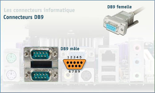
Le connecteur DB-9

Connecteur Interface souris SGI (modèle 021-0004-002) (DB9)
| Schéma | Brochage |
|---|---|
 | 1 +5V |
| 2 -5V | |
| 3 | |
| 4 | |
| 5 MTXD (data) | |
| 6 | |
| 7 | |
| 8 | |
| 9 GND |
Connecteur Moniteur CGA (DB9 VIDEO)
| Schéma | Brochage |
|---|---|
 | 1 GND (Masse) |
| 2 GND (Masse) | |
| 3 RED (Signal vidéo rouge) | |
| 4 GREEN (Signal vidéo vert) | |
| 5 BLUE (Signal vidéo bleu) | |
| 6 Intensity (Intensité couleur) | |
| 7 RESERVED (Réservé) | |
| 8 HSYNC (Sync. Horizontale) | |
| 9 VSYNC (Sync. Verticale) |
Connecteur Moniteur EGA (DB9 VIDEO)
| Schéma | Brochage |
|---|---|
 | 1 GND (Masse) |
| 2 SRED (Secondary Red Video) Signal vidéo rouge secondaire | |
| 3 PRED (Primary Red Video) Signal vidéo rouge principal | |
| 4 PGREEN (Primary Green Video) Signal vidéo vert principal | |
| 5 PBLUE (Primary Blue Video) Signal vidéo bleu principal | |
| 6 SGREEN (Secondary Green Video) Signal vidéo vert secondaire | |
| 7 SBLUE (Secondary Blue Video) Signal vidéo bleu secondaire | |
| 8 HSYNC (Sync. Horizontale) | |
| 9 VSYNC (Sync. Verticale) |
Connecteur Moniteur MDA (DB9 VIDEO)
| Schéma | Brochage |
|---|---|
 | 1 GND |
| 2 GND | |
| 3 NC | |
| 4 NC | |
| 5 NC | |
| 6 intensity | |
| 7 video | |
| 8 HSYNC (Sync. Horizontale) | |
| 9 VSYNC (Sync. Verticale) |
Connecteur Moniteur VGA (DB9 VIDEO)
| Schéma | Brochage |
|---|---|
 | 1 RED (Signal vidéo rouge) |
| 2 GREEN (Signal vidéo vert) | |
| 3 BLUE (Signal vidéo bleu) | |
| 4 HSYNC (Sync. Horizontale) | |
| 5 VSYNC (Sync. Verticale) | |
| 6 RGND (Red Ground (Return)) | |
| 7 GGND (Green Ground (Return)) | |
| 8 BGND (Blue Ground (Return)) | |
| 9 SGND (Sync Ground) |
Connecteur Moniteur multisync NEC (DB9 VIDEO)
| Schéma | Brochage |
|---|---|
 | 1 RED (Signal vidéo rouge) |
| 2 GREEN (Signal vidéo vert) | |
| 3 BLUE (Signal vidéo bleu) | |
| 4 HSYNC (Sync. Horizontale) | |
| 5 VSYNC (Sync. Verticale) | |
| 6 RGND (Red Ground (Return)) | |
| 7 GGND (Green Ground (Return)) | |
| 8 BGND (Blue Ground (Return)) | |
| 9 SGND (Sync Ground) |
Connecteur RS-232 (9 broches) (DB9)
| Schéma | Brochage |
|---|---|
 | 1 CD porteuse - carrier detect |
| 2 RD RX - Données reçues | |
| 3 TD TX - Données transmises | |
| 4 DTR DTR - data terminal ready | |
| 5 GND Masse | |
| 6 DSR DSR - data set ready | |
| 7 RTS RTS - request to send | |
| 8 CTS CTS - clear to send | |
| 9 RI RING - ring indicator | |
Les ports série peuvent se présenter de cette forme. | |
Connecteur Signal sur UPS Minuteman (DB9)
| Schéma | Brochage |
|---|---|
 | 1 NC |
| 2 Alimentation Batterie | |
| 3 NC | |
| 4 Commun (idem pin 7) | |
| 5 Batterie basse | |
| 6 RS-232 shutdown | |
| 7 Commun (idem pin 4) | |
| 8 Ground shutdown (A500 and above, reservé on < A500) | |
| 9 Reservé | |
Remarques : Pins 2 et 5 sont connectées au commun quand elles sont actives. | |
English translation
You have asked to visit this site in English. For now, only the interface is translated, but not all the content yet.If you want to help me in translations, your contribution is welcome. All you need to do is register on the site, and send me a message asking me to add you to the group of translators, which will give you the opportunity to translate the pages you want. A link at the bottom of each translated page indicates that you are the translator, and has a link to your profile.
Thank you in advance.
Document created the 09/10/2003, last modified the 26/10/2018
Source of the printed document:https://www.gaudry.be/en/connecteur-db9.html
The infobrol is a personal site whose content is my sole responsibility. The text is available under CreativeCommons license (BY-NC-SA). More info on the terms of use and the author.


